
Page 24 - DSP Integrated Circuits
P. 24
1.5 DSP Systems 9
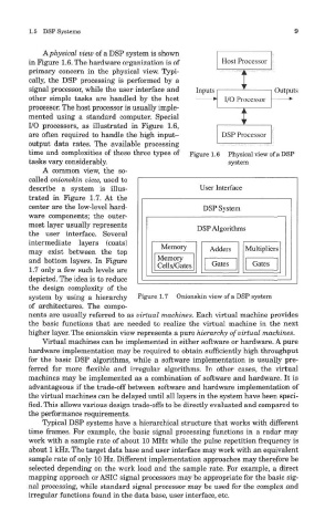
PL physical view of a DSP system is shown
in Figure 1.6. The hardware organization is of
primary concern in the physical view. Typi-
cally, the DSP processing is performed by a
signal processor, while the user interface and
other simple tasks are handled by the host
processor. The host processor is usually imple-
mented using a standard computer. Special
I/O processors, as illustrated in Figure 1.6,
are often required to handle the high input-
output data rates. The available processing
time and complexities of these three types of Figure 1.6 Physical view of a DSP
tasks vary considerably. system
A common view, the so-
called onionskin view, used to
describe a system is illus-
trated in Figure 1.7. At the
center are the low-level hard-
ware components; the outer-
most layer usually represents
the user interface. Several
intermediate layers (coats)
may exist between the top
and bottom layers. In Figure
1.7 only a few such levels are
depicted. The idea is to reduce
the design complexity of the
system by using a hierarchy Figure 1.7 Onionskin view of a DSP system
of architectures. The compo-
nents are usually referred to as virtual machines. Each virtual machine provides
the basic functions that are needed to realize the virtual machine in the next
higher layer. The onionskin view represents a pure hierarchy of virtual machines.
Virtual machines can be implemented in either software or hardware. A pure
hardware implementation may be required to obtain sufficiently high throughput
for the basic DSP algorithms, while a software implementation is usually pre-
ferred for more flexible and irregular algorithms. In other cases, the virtual
machines may be implemented as a combination of software and hardware. It is
advantageous if the trade-off between software and hardware implementation of
the virtual machines can be delayed until all layers in the system have been speci-
fied. This allows various design trade-offs to be directly evaluated and compared to
the performance requirements.
Typical DSP systems have a hierarchical structure that works with different
time frames. For example, the basic signal processing functions in a radar may
work with a sample rate of about 10 MHz while the pulse repetition frequency is
about 1 kHz. The target data base and user interface may work with an equivalent
sample rate of only 10 Hz. Different implementation approaches may therefore be
selected depending on the work load and the sample rate. For example, a direct
mapping approach or ASIC signal processors may be appropriate for the basic sig-
nal processing, while standard signal processor may be used for the complex and
irregular functions found in the data base, user interface, etc.