
Page 23 - DSP Integrated Circuits
P. 23
8 Chapter 1 DSP Integrated Circuits
A behavioral description is an input—output description that defines the
required action of a system in response to prescribed inputs. The description of the
behavior may not include directions about the means of implementation or perfor-
mance measures such as speed of operation, size, and power dissipation unless
they directly affect the application.
A functional description defines the manner in which the system is operated
to perform its function. Of main interest in the functional view are the signal pro-
cessing aspects of the DSP system. Furthermore, input and output data rates and
buffer sizes are important issues in the functional view.
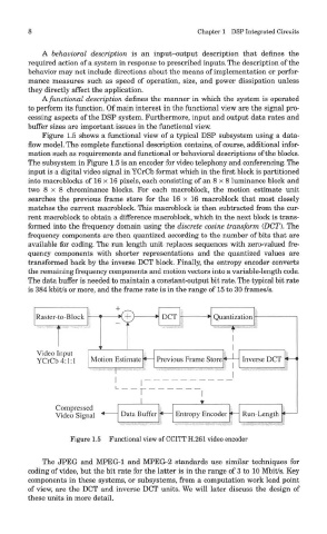
Figure 1.5 shows a functional view of a typical DSP subsystem using a data-
flow model. The complete functional description contains, of course, additional infor-
mation such as requirements and functional or behavioral descriptions of the blocks.
The subsystem in Figure 1.5 is an encoder for video telephony and conferencing. The
input is a digital video signal in YCrCb format which in the first block is partitioned
into macroblocks of 16 x 16 pixels, each consisting of an 8 x 8 luminance block and
two 8x 8 chrominance blocks. For each macroblock, the motion estimate unit
searches the previous frame store for the 16 x 16 macroblock that most closely
matches the current macroblock. This macroblock is then subtracted from the cur-
rent macroblock to obtain a difference macroblock, which in the next block is trans-
formed into the frequency domain using the discrete cosine transform (DCT). The
frequency components are then quantized according to the number of bits that are
available for coding. The run length unit replaces sequences with zero-valued fre-
quency components with shorter representations and the quantized values are
transformed back by the inverse DOT block. Finally, the entropy encoder converts
the remaining frequency components and motion vectors into a variable-length code.
The data buffer is needed to maintain a constant-output bit rate. The typical bit rate
is 384 kbit/s or more, and the frame rate is in the range of 15 to 30 frames/s.
Figure 1.5 Functional view of CCITT H.261 video encoder
The JPEG and MPEG-1 and MPEG-2 standards use similar techniques for
coding of video, but the bit rate for the latter is in the range of 3 to 10 Mbit/s. Key
components in these systems, or subsystems, from a computation work load point
of view, are the DCT and inverse DCT units. We will later discuss the design of
these units in more detail.