
Page 259 - DSP Integrated Circuits
P. 259
244 Chapter 6 DSP Algorithms
6.6.3 Shimming Delay
If two paths in a computation graph have a common origin and a common end
node, then the data streams in these two paths have to be synchronized at the
summation node by introducing a delay in the fastest path. For example, execution
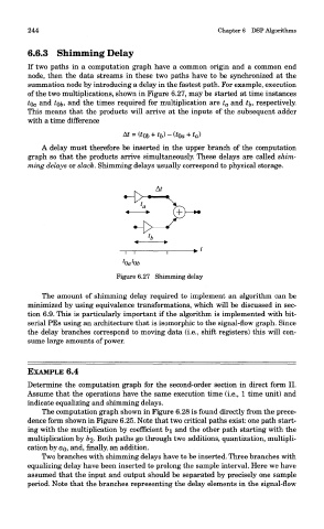
of the two multiplications, shown in Figure 6.27, may be started at time instances
tQ a and tQb, and the times required for multiplication are t a and t^, respectively.
This means that the products will arrive at the inputs of the subsequent adder
with a time difference
A delay must therefore be inserted in the upper branch of the computation
graph so that the products arrive simultaneously. These delays are called shim-
ming delays or slack. Shimming delays usually correspond to physical storage.
Figure 6.27 Shimming delay
The amount of shimming delay required to implement an algorithm can be
minimized by using equivalence transformations, which will be discussed in sec-
tion 6.9. This is particularly important if the algorithm is implemented with bit-
serial PEs using an architecture that is isomorphic to the signal-flow graph. Since
the delay branches correspond to moving data (i.e., shift registers) this will con-
sume large amounts of power.
EXAMPLE 6.4
Determine the computation graph for the second-order section in direct form II.
Assume that the operations have the same execution time (i.e., 1 time unit) and
indicate equalizing and shimming delays.
The computation graph shown in Figure 6.28 is found directly from the prece-
dence form shown in Figure 6.25. Note that two critical paths exist: one path start-
ing with the multiplication by coefficient 61 and the other path starting with the
multiplication by 62- Both paths go through two additions, quantization, multipli-
cation by ao, and, finally, an addition.
Two branches with shimming delays have to be inserted. Three branches with
equalizing delay have been inserted to prolong the sample interval. Here we have
assumed that the input and output should be separated by precisely one sample
period. Note that the branches representing the delay elements in the signal-flow