
Page 264 - DSP Integrated Circuits
P. 264
6.7 Equivalence Transformations 249
One integer delay ele-
ment is obtained between
the adaptors and one T/2-
delay element in series with
the A2-input. The latter
serves no purpose and can Figure 6.33 Pipelined structure with integer delay
therefore be removed, since elements
the input signal A% = 0. Note
that the total delay in the
recursive loop is unchanged.
The outputs have been delayed by T/2 with respect to the initial network. In fact,
this modification is a form of pipelining, which will be discussed in section 6.8.
6.7.2 Timing of Signal-flow Graphs
Equivalence transformations can be used to determine the proper timing of the
operations in signal-flow graphs as well as proper control signals. Such signal-flow
graphs can easily be transformed into proper computation graphs. Of particular
interest is to determine the required amount of shimming delay as well as the
positions of the D flip-flops. The technique presented next leads to the same
results as methods based on cut set transformations [15]. We will demonstrate the
technique by means of an example.
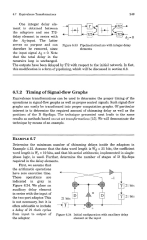
EXAMPLE 6.7
Determine the minimum number of shimming delays inside the adaptors in
Example 4.12. Assume that the data word length is Wj = 21 bits, the coefficient
word length is W c = 10 bits, and that bit-serial arithmetic, implemented in single-
phase logic, is used. Further, determine the number of stages of D flip-flops
required in the delay elements.
First, we assume that
the arithmetic operations
have zero execution time.
These operations are
indicated in gray in
Figure 6.34. We place an
auxiliary delay element
in series with the input of
the two-port adaptor. This
is not necessary, but it is
often advisable to include
a delay of 21 clock cycles
from input to output of Figure 6.34 Initial configuration with auxiliary delay
the adaptor. element at the input