
Page 265 - DSP Integrated Circuits
P. 265
250 Chapters DSP Algorithms
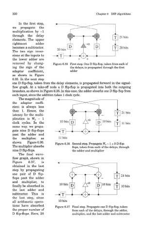
In the first step,
we propagate the
multiplication by -1
through the delay
elements. The upper
rightmost adder
becomes a subtractor.
The two sign inver-
sions at the inputs to
the lower adder are
removed by chang- Figure 6.35 First step. One D flip-flop, taken from each of
ing the sign of the the delays, is propagated through the first
adaptor coefficient, oHrJoy
as shown in Figure
6.35. In the next step
one D flip-flop, taken from the delay elements, is propagated forward in the signal-
flow graph. At a take-off node a D flip-flop is propagated into both the outgoing
branches, as shown in Figure 6.35. In this case, the adder absorbs one D flip-flop from
each input, since the addition takes 1 clock cvcle.
The magnitude of
the adaptor coeffi-
cient is always less
than 1. Hence, the
latency for the multi-
plication is W c - 1
clock cycles. In the
same way, we propa-
gate nine D flip-flops
past the adder and
the multiplier, as
shown Figure 6.36. Figure 6.36 Second step. Propagate W c-l = 9D flip-
The multiplier absorbs flops, taken from each of the delays, through
nine D flip-flops. the adder and multiplier
The final wave-
flow graph, shown in
Figure 6.37, is
obtained in the last
step by propagating
one pair of D flip-
flops past the adder
and multiplier, to
finally be absorbed in
the last adder and
subtractor. This is
the last step, since
all arithmetic opera-
tions have absorbed Figure 6.37 Final step. Propagate one D flip-flop, taken
the proper number of from each of the delays, through the adder,
D flip-flops. Here, 20 multiplier, and the last adder and subtractor