
Page 263 - DSP Integrated Circuits
P. 263
248 ChapterG DSP Algorithms
6.7.1 Essentially Equivalent Networks
The condition under which a shift-invariant network in series with a set of delay ele-
ments may be changed is given next [9]. This modification is also called retiming [15].
Theorem 6.3
If an arbitrary, nonlinear, time-varying discrete time network, N n, has
delay elements in series with all inputs (outputs), then all the delays can
be moved to the outputs (inputs) and the properties of N n shifted, accord-
ing to Figure 6.31, without changing the input-output behavior of the
composite system. N n and N n+i denote the properties of the network with
reference to samples n and n+l, respectively.
—4x1-* ~+ , ,
—> —HT|—>
->[Y}-> N n ^^ __> N n+l
—+ —»pr}-*
—^pr}-* —*
Figure 6.31 Networks with equivalent input-output behavior
For a shift-invariant system we have N n = N n_ HQ for all HQ. Two networks that
can be transformed into one another by the equivalence transformations just
described, except for different (positive or negative) delays appearing in their
input and output branches, are called essentially equivalent networks [9]. A delay
element cannot be propagated into a recursive loop. However, the positions of the
delay elements in a recursive loop can be changed as shown in Example 6.6. The
latency of the algorithm may be affected by such a change, but the maximum sam-
ple rate is unaffected.
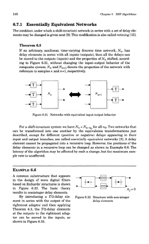
EXAMPLE 6.6
A common substructure that appears
in the design of wave digital filters
based on Richards' structures is shown
in Figure 6.32. The basic theory
results in noninteger delay elements.
By introducing a T/2-delay ele- Figure 6.32 Structure with non-integer
ment in series with the output of the delay elements
rightmost adaptor and then applying
Theorem 6.3, the T/2-delay elements
at the outputs to the rightmost adap-
tor can be moved to the inputs, as
shown in Figure 6.33.