
Page 268 - DSP Integrated Circuits
P. 268
6.8 Interleaving and Pipelining 253
EXAMPLE 6.8
Show that it is possible to reduce the length of the critical loop in the filter shown
in Figure 6.30, and thereby reduce the required number of clock cycles per sample,
by performing a numerical equivalence transformation (reordering of the addi-
tions) on the wave-flow graph.
In tms case, the crit-
ical loop contains two
such additions. To dem-
onstrate the transforma-
tion we first move
addition #3 across the
delay elements as shown
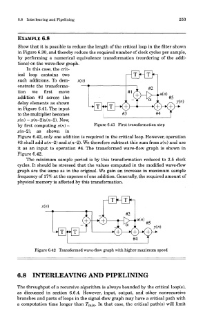
in Figure 6.41. The input
to the multiplier becomes
x(n) - x(n-2)u(n-2). Now,
by first computing x(n) - Figure 6.41 First transformation step
x\n-A), as snown in
Figure 6.42, only one addition is required in the critical loop. However, operation
#3 shall add u(n-2) and x(n-2). We therefore subtract this sum from x(n) and use
it as an input to operation #4. The transformed wave-flow graph is shown in
Figure 6.42.
The minimum sample period is by this transformation reduced to 2.5 clock
cycles. It should be stressed that the values computed in the modified wave-flow
graph are the same as in the original. We gain an increase in maximum sample
frequency of 17% at the expense of one addition. Generally, the required amount of
physical memory is affected by this transformation.
Figure 6.42 Transformed wave-flow graph with higher maximum speed
6.8 INTERLEAVING AND PIPELINING
The throughput of a recursive algorithm is always bounded by the critical loop(s),
as discussed in section 6.6.4. However, input, output, and other nonrecursive
branches and parts of loops in the signal-flow graph may have a critical path with
a computation time longer than T mi n. In that case, the critical path(s) will limit