
Page 271 - DSP Integrated Circuits
P. 271
256 Chapters DSP Algorithms
EXAMPLE 6.9
Determine the precedence relations for the operations in the structure shown in
Figure 6.46 [6, 7]. Introduce pipelining and compare the parallelism between the
two structures.
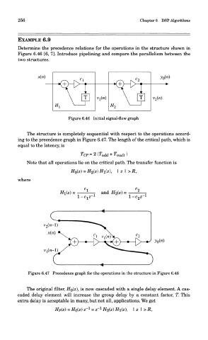
Figure 6.46 Initial signal-flow graph
The structure is completely sequential with respect to the operations accord-
ing to the precedence graph in Figure 6.47. The length of the critical path, which is
equal to the latency, is
Note that all operations lie on the critical path. The transfer function is
where
Figure 6.47 Precedence graph for the operations in the structure in Figure 6.46
The original filter, HQ(Z), is now cascaded with a single delay element. A cas-
caded delay element will increase the group delay by a constant factor, T. This
extra delay is acceptable in many, but not all, applications. We get