
Page 274 - DSP Integrated Circuits
P. 274
6.8 Interleaving and Pipelining 259
To summarize, the two critical paths are broken into pieces of equal size. The
last stage consists of only one addition. The wave-flow graph is partitioned into 10
paths, each performing an addition and a "half-multiplication. Hence, the multi-
pliers should have two pipeline stages. The last stage in the upper branch corre-
sponds to a shimming delay of length T mi n. The group delay of the filter has,
because of the pipelining, increased by a constant factor Ar^ = 6 T mi n.
6.8.3 Functional and Structural Pipelines
Both algorithms and hardware structures can be pipelined. In classical pipe-
lines, only one operation is executed by each pipeline stage (PE) separated by
registers (delay elements). A PE is allocated to each stage of the pipeline. The
pipeline stages do not share resources. This leads to a fixed and simple communi-
cation pattern between the processors. This case is often referred to as a struc-
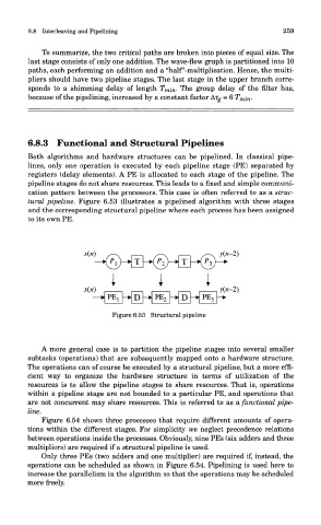
tural pipeline. Figure 6.53 illustrates a pipelined algorithm with three stages
and the corresponding structural pipeline where each process has been assigned
to its own PE.
Figure 6.53 Structural pipeline
A more general case is to partition the pipeline stages into several smaller
subtasks (operations) that are subsequently mapped onto a hardware structure.
The operations can of course be executed by a structural pipeline, but a more effi-
cient way to organize the hardware structure in terms of utilization of the
resources is to allow the pipeline stages to share resources. That is, operations
within a pipeline stage are not bounded to a particular PE, and operations that
are not concurrent may share resources. This is referred to as a functional pipe-
line.
Figure 6.54 shows three processes that require different amounts of opera-
tions within the different stages. For simplicity we neglect precedence relations
between operations inside the processes. Obviously, nine PEs (six adders and three
multipliers) are required if a structural pipeline is used.
Only three PEs (two adders and one multiplier) are required if, instead, the
operations can be scheduled as shown in Figure 6.54. Pipelining is used here to
increase the parallelism in the algorithm so that the operations may be scheduled
more freely.