
Page 279 - DSP Integrated Circuits
P. 279
264 Chapters DSP Algorithms
Coefficients c^ are selected such that coefficients d^ are zero for k = I,..., M.
The maximum sample rate has thereby been increased by a factor M. The corre-
sponding difference equation is
The output is computed from the N past values that are clustered in time, i.e.,
y(n-M-l), y(n-M-2), y(n-M-3),..., y(n-M-N). We illustrate the clustered look-
ahead pipelining with two examples.
EXAMPLE 6.11
Use clustered look-ahead pipelining to increase the maximum sample rate of a
first-order filter by a factor two.
The original transfer function is
We form the new transfer function
and select c\ = 6^ which yields
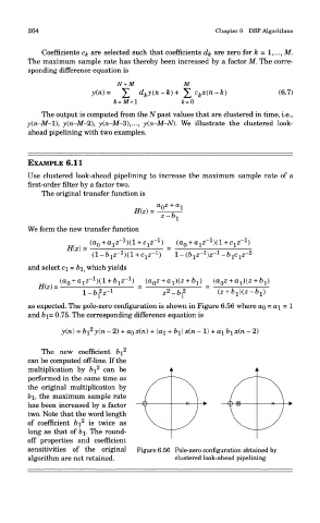
as expected. The pole-zero configuration is shown in Figure 6.56 where OQ = ai = 1
and 61= 0.75. The corresponding difference equation is
The new coefficient 6i 2
can be computed off-line. If the
2
multiplication by 6j can be
performed in the same time as
the original multiplication by
&1, the maximum sample rate
has been increased by a factor
two. Note that the word length
2
of coefficient &i is twice as
long as that of 61. The round-
off properties and coefficient
sensitivities of the original Figure 6.56 Pole-zero configuration obtained by
algorithm are not retained. clustered look-ahead pipelining