
Page 280 - DSP Integrated Circuits
P. 280
6.9 Algorithm Transformations 265
EXAMPLE 6.12
Use clustered look-ahead pipelining to increase the maximum sample rate of the
second-order filter by a factor two.
The original transfer function is
We form the new transfer function
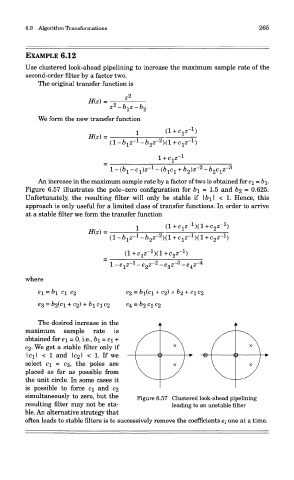
An increase in the maximum sample rate by a factor of two is obtained for c\ = b\,
Figure 6.57 illustrates the pole-zero configuration for b\ = 1.5 and b% = 0.625.
Unfortunately, the resulting filter will only be stable if I b\ I < 1. Hence, this
approach is only useful for a limited class of transfer functions. In order to arrive
at a stable filter we form the transfer function
where
The desired increase in the
maximum sample rate is
obtained for e\ = 0, i.e., b\ = c\ +
C2- We get a stable filter only if
I ci I < 1 and 1021 < 1. If we
select GI = 02, the poles are
placed as far as possible from
the unit circle. In some cases it
is possible to force c\ and 02
simultaneously to zero, but the Figure 6.57 Clustered look-ahead pipelining
resulting filter may not be sta- leading to an unstable filter
ble. An alternative strategy that
often leads to stable filters is to successively remove the coefficients ei one at a time.