
Page 283 - DSP Integrated Circuits
P. 283
268 Chapters DSP Algorithms
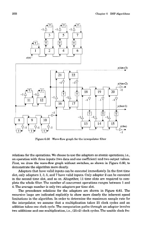
Figure 6.60 Wave-flow graph for the interpolator filter
relations for the operations. We choose to use the adaptors as atomic operations, i.e.,
an operation with three inputs (two data and one coefficient) and two output values.
First, we draw the wave-flow graph without switches, as shown in Figure 6.60, to
demonstrate the algorithm more clearly.
Adaptors that have valid inputs can be executed immediately. In the first time
slot, only adaptors 1, 3, 5, and 7 have valid inputs. Only adaptor 2 can be executed
in the second time slot, and so on. Altogether, 11 time slots are required to com-
plete the whole filter. The number of concurrent operations ranges between 1 and
4. The average number is only two adaptors per time slot.
The precedence relations for the adaptors are shown in Figure 6.61. The
recursive loops are indicated explicitly to show more clearly the inherent speed
limitations in the algorithm. In order to determine the maximum sample rate for
the interpolator, we assume that a multiplication takes 21 clock cycles and an
addition takes one clock cycle. The computation paths through an adaptor involve
two additions and one multiplication, i.e., (21+2) clock cycles. The usable clock fre-