
Page 288 - DSP Integrated Circuits
P. 288
Problems 273
(b) Write the system of difference equation in computable order.
(c) Write a program, using a high-level language, to implement the filter
structure.
6.12 Insert shimming delays into the Cooley-Tukey butterfly. Assume that a real
addition takes 1 time unit and a real multiplication takes 24 time units.
Further, a complex multiplication is realized with four real multiplications.
Note that more efficient ways exist to realize a complex multiplication using
fewer real multiplications.
6.13 Determine the number of shimming delays and D flip-flops needed to
implement the second-order allpass sections shown in Figure 5.10, using bit-
serial arithmetic. Assume that the coefficient word length W c = 13 bits, data
word length W^ = 19 bits, and that twos-complement truncation is performed
following the multiplications. Further, a correction is made in front of the
delay elements by adding a 1 to the least significant bit if the value is
negative; otherwise a 0 is added.
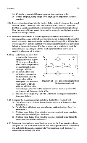
6.14 (a) Determine the wave-flow
graph for the three-port
adaptor, shown in Figure
P6.14, in precedence form
when the basic operations
are multiplication and
two-input addition.
(b) Bit-serial adders and
multipliers are used. A
multiplication takes 12
clock cycles, which
Figure P6.14 Tree-port series adaptor. Port
correspond to a coefficient
word length of 12 bits, 3 is the dependent port
while an addition takes
one clock cycle. Determine the maximum sample frequency when the
maximum clock frequency is 60 MHz.
(c) The data word length W^ = 21 bits. Determine the required amount of
shimming delays.
6.15 Compare the maximum sample rate for a digital filter realized with
(a) Cascade form with first- and second-order sections in direct form I or
direct form II.
(b) Parallel form with first- and second-order sections in direct form I or
direct form II.
(c) A lattice wave digital filter with the branches realized using circulator
structures (cascaded allpass sections).
d) A lattice wave digital filter with the branches realized using Richards
structures (cascaded unit elements).
6.16 Determine the maximum sampling frequency for the filter structure shown
in Figure P6.16 if a bit-serial addition and a multiplication have latencies of
one and eight clock cycles, respectively. The maximum clock frequency is
assumed to be at least 100 MHz.