
Page 282 - DSP Integrated Circuits
P. 282
6.10 Interpolator, Cont. 267
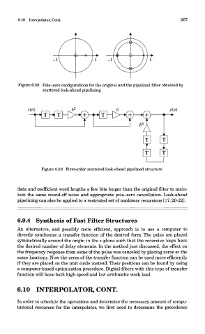
Figure 6.58 Pole-zero configurations for the original and the pipelined filter obtained by
scattered look-ahead pipelining
Figure 6.59 First-order scattered look-ahead pipelined structure
data and coefficient word lengths a few bits longer than the original filter to main-
tain the same round-off noise and appropriate pole-zero cancellation. Look-ahead
pipelining can also be applied to a restricted set of nonlinear recursions [17,20-22].
6.9.4 Synthesis of Fast Filter Structures
An alternative, and possibly more efficient, approach is to use a computer to
directly synthesize a transfer function of the desired form. The poles are placed
symmetrically around the origin in the z-plane such that the recursive loops have
the desired number of delay elements. In the method just discussed, the effect on
the frequency response from some of the poles was canceled by placing zeros at the
same locations. Now the zeros of the transfer function can be used more efficiently
if they are placed on the unit circle instead. Their positions can be found by using
a computer-based optimization procedure. Digital niters with this type of transfer
function will have both high speed and low arithmetic work load.
6.10 INTERPOLATOR, CONT.
In order to schedule the operations and determine the necessary amount of compu-
tational resources for the interpolator, we first need to determine the precedence