
Page 272 - DSP Integrated Circuits
P. 272
6.8 Interleaving and Pipelining 257
The order of the linear, shift-invariant filters and the delay element can be
interchanged. Hence, we get
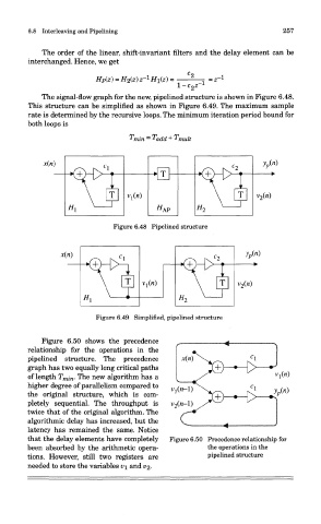
The signal-flow graph for the new, pipelined structure is shown in Figure 6.48.
This structure can be simplified as shown in Figure 6.49. The maximum sample
rate is determined by the recursive loops. The minimum iteration period bound for
both loops is
Figure 6.48 Pipelined structure
Figure 6.49 Simplified, pipelined structure
Figure 6.50 shows the precedence
relationship for the operations in the
pipelined structure. The precedence
graph has two equally long critical paths
of length T mi n. The new algorithm has a
higher degree of parallelism compared to
the original structure, which is com-
pletely sequential. The throughput is
twice that of the original algorithm. The
algorithmic delay has increased, but the
latency has remained the same. Notice
that the delay elements have completely Figure 6.50 Precedence relationship for
been absorbed by the arithmetic opera- the operations in the
tions. However, still two registers are pipelined structure
needed to store the variables v\ and v%.