
Page 273 - DSP Integrated Circuits
P. 273
258 Chapter 6 DSP Algorithms
EXAMPLE 6.10
Determine how many
effective pipelining
stages can be introduced
into the lattice wave dig-
ital filter shown in Fig-
ures 6.51. Assume that
all adaptor coefficients
have the same word
length and that latches
can be inserted inside
the multipliers, i.e., they
can be pipelined.
First, we note that
the critical loop(s) deter-
mines the maximum
sample rate and that it
is not possible to further
increase the sample rate
by pipelining. We have
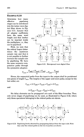
the same recursive com- Figure 6.51 Bireciprocal wave digital filter
putation paths through
the symmetric adaptors
Hence, the sequential paths from the input to the output shall be partitioned
into pieces of length T mi n. The lengths of the upper and lower paths, except for the
last adder, are
and
Six delay elements can be propagated into each of the filter branches. Thus,
only seven stages of pipelining can be used, as illustrated in Figure 6.52, where
only those operations belonging to the critical paths are shown.
Figure 6.52 Pipelining levels obtained by propagating delays from the input side. Note
that only the critical paths in the two branches are shown