
Page 306 - DSP Integrated Circuits
P. 306
7.3 FFT Processor, Cont. 291
Each of these processes will later be mapped to a hardware structure. We
notice that each of the input and output phases is controlled by a single process
that can be realized by a counter (0 to N-l). In fact, the counter can be of arbitrary
type, i.e., up or down counter or in any order as long as all values are counted. This
fact will later be used to simplify the implementation.
The FFT phase is controlled by two nested control processes that can be realized
by using two counters and some simple logic. Hence, using this approach the control
structure becomes obvious and simple to map to an efficient hardware structure.
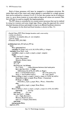
The program for the third and final iteration is shown in Box. 7.5.
—Sande-Tukey FFT. Third design iteration and a new entity
~ entity ent_third is
— port(data : in complex; data_ut: out complex);
-- end ent_third;
--Filename: FFT_ST3.VHD
architecture beh_ST3 of ent_FFT is
begin
Main: process(data)
variable Ns, Stage, ind, m, kl, k2, klNs, k2Ns, p : integer;
variable Wcos, Wsin : real;
variable x_tmpl, x_tmp2, x_tmp3, x_tmp4 : complex
begin
for i in 0 to N-l loop
Input_Data(data);
Memory_Write(i, data);
end loop;
Ns := N;
for Stage in 1 to M loop
Ns := Ns/2; —index distance between dual node pairs
for m in 0 to ((N/4) - 1) loop
Addresses(p, kl, klNs, k2, k2Ns, m, Stage);
Wcos := cos(TwoPiN*real(p)); -W to the power of p
Wsin := -sin(TwoPiN*real(p)); ~W = exp(-j2pi7N)
Memory(Rflag, x_tmpl, x_tmp2, x_tmp3, x_tmp4, kl, klNs, k2, k2Ns):
Butterfly(x_tmpl, x_tmp2, Wcos, Wsin); -Concurrent
if (Stage =1) then
Butterfly(x_tmp3, x_tmp4, Wsin, -Wcos); —Butterflies
else
Butterfly(x_tmp3, x_tmp4, Wcos, Wsin);
end if;
Memory(Wflag, x_tmpl, x_tmp2, x_tmp3, x_tmp4, kl, klNs, k2, k2Ns)
end loop; -for loop
end loop; —for loop
for i in 0 to N - 1 loop
ind := Digit_Reverse(i);
Memory_Read(ind, data);
data_ut <= Output_Data(data);
end loop;
end process Main;
end beh_ST3;
Box 7.5 Third design iteration