
Page 310 - DSP Integrated Circuits
P. 310
7.5 Scheduling Formulations 295
critical loop of the SFG contains
more than one delay element, the
critical path restricting the sample
period can not be found. Also, non-
uniform boundaries make it more
difficult to evaluate the cost func-
tion since operations belonging to
different sample intervals are per-
formed concurrently. Figure 7.9 Schedule with nonuniform
boundaries
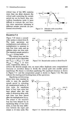
EXAMPLE 7.1
Figure 7.10 shows a second-
order section in direct form II.
The basic operations are
multiplication and addition. A
multiplication is assumed to
take four time units and an
addition takes one time unit.
The required sample period is
Tsample = 10 time units.
The critical loop and the
critical path of this algorithm
are T mui t + 2T add = 6 and Figure 7.10 Second-order section in direct form II
2T mui t + 3T add = 11 time
units, respectively, Hence, to
achieve the desired sample rate, we must either duplicate some computational
resources or introduce delays to divide the critical path into smaller pieces
(pipelining). We choose to introduce pipelining. The pipelined structure is shown
in Figure 7.11 and the computation graph is shown in Figure 7.12. The dots
indicate the starting and finishing times of the operations.
Hiquaiizmg ana smmming
delays have been inserted in
order to meet the specified
sample period by extending
all computational paths to 10
time units. An equalizing
delay of four time units has
been placed after the last
adder. A shimming delay, with
unit time, has been placed
after the multiplication by OQ-
The output in the recursive
loop has been delayed by an
equalizing delay of four time
units, so that the time differ-
ence between the input and
output is 10 time units. The Figure 7.11 Second-order section with pipelining