
Page 315 - DSP Integrated Circuits
P. 315
300 Chapter 7 DSP System Design
where {. } denotes the least common multiple. Generally, a search over all reason-
able values of K must be done in order to find the minimum resource schedule.
EXAMPLE 7.2
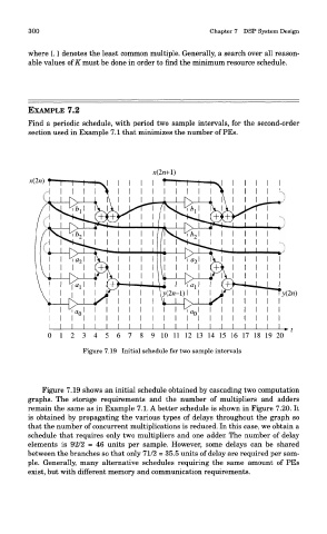
Find a periodic schedule, with period two sample intervals, for the second-order
section used in Example 7.1 that minimizes the number of PEs.
Figure 7.19 Initial schedule for two sample intervals
Figure 7.19 shows an initial schedule obtained by cascading two computation
graphs. The storage requirements and the number of multipliers and adders
remain the same as in Example 7.1. A better schedule is shown in Figure 7.20. It
is obtained by propagating the various types of delays throughout the graph so
that the number of concurrent multiplications is reduced. In this case, we obtain a
schedule that requires only two multipliers and one adder. The number of delay
elements is 92/2 = 46 units per sample. However, some delays can be shared
between the branches so that only 71/2 = 35.5 units of delay are required per sam-
ple. Generally, many alternative schedules requiring the same amount of PEs
exist, but with different memory and communication requirements.