
Page 320 - DSP Integrated Circuits
P. 320
7.5 Scheduling Formulations 305
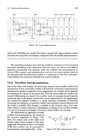
Figure 7.24 Logic implementation
clock cycles (400 MHz) per sample. This leads to significantly higher speed as well as
less chip area and power consumption compared to the bit-parallel implementation,
The preceding examples show that the hardware resources can be minimizec
by proper scheduling of the operations. However, there are still several difficult
questions unanswered. For example, what are suitable cost measurements ir
terms of PEs, memory, and communication and over how many sample intervals
the planning shall be performed. Further, it is important to note that cyclic plan-
ning problems are much more difficult than acyclic problems.
7.5.5 Overflow And Quantization
Due to the finite word lengths, the processing elements must handle overflow anc
quantization of data. Generally, overflow is detected by introduction of guard bits b}
extending the number of sign-bits (two's-complement). An overflow can be detected
by comparing the sign-bit to the guard bits. If the bit values differ, an overflow has
occurred. Minimizing the impact of an overflow could, for example, be performed bj
setting the data to the largest number that can be represented (or the largest nega
tive number for negative overflow), i.e., using saturation arithmetic. In bit-serial
processing, the detection of a possible overflow and correction must be delayed until
the result is available. This becomes a problem in the recursive parts of an algo
rithm, where it causes a decrease in throughput. A solution to the overflow problerr
is to use an increased word length in the loop so that overflow can not occur.
We will describe an approach to handle
overflow and quantization by the means of
the recursive algorithm in Figure 7.25.
Here, the output node of the adder may
assume values twice as large as the input
magnitude. Assuming an input word length
of Wd bits, overflow can be prevented by
increasing the word length to Wj + 1 bits. Figure 7.25 First-order recursive filter