
Page 321 - DSP Integrated Circuits
P. 321
306 Chapter 7 DSP System Design
Quantization of data must also be performed in recursive parts of an algo-
rithm. The solution is to truncate the data somewhere in a loop. Rounding can be
performed by adding a one to the bit-position to the right of the least-significant
bit before the truncation takes place.
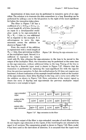
The filter in Figure 7.25 has a
e
coefficient of a = (0.5)io = (0.1)2, i- -> x(n} : ^x H y(ri)
a word length W c of 2 bits. Generally, X:pH^ H> lQhp
an input to a serial/parallel multi-
plier needs to be sign-extended to ^=^—Or} 1
W^ + W c — 1 bits, i.e., one additional
bit is required in the example. It is o
advantageous to move the sign- y
« H—T~r~\\
^
extension across the addition as x(ri) —*• s.e. -*(+)—p-^ Q ~~*" - ' T *
S-e
shown in Figure 7.26.
First, the result of the addition
is represented with a word length of —OLh
W^ + 1 bits, thus preventing overflow Figure 7.26 Moving the sign-extension (s.e.)
at the multipliers input. Second, it is
sufficient to represent the output
word with W^ bits, allowing the sign-extension in the loop to be moved to the
output of the multiplier. Then, the truncation may be performed at the same time
as the sign-extension, without additional delay in the loop. Timing of the bits in
the loop for a three-bit input word is shown in Figure 7.27. Observe that the
truncation is performed by replacing the least-significant bit with the sign-bit
from the previous operation. In fact, the multiplication by 0.5 does not require any
hardware. A direct realization of the example would include a latch at the location
of the sign-extension, three delay flip-flops in the loop, and a carry-save adder for
the addition as shown in Figure 7.28. Here, activation of the control signal CQ
clears the carry D flip-flop and sign-extends the previous multiplier output
whenever a new sample is input.
Figure 7.27 Sign-extension in the filter
Since the output of the filter is sign-extended, cascades of such filter sections
do not require sign-extension at the inputs, if the word lengths are selected to be
equal in all sections. The computation graph is shown in Figure 7.29. Here, model
0 has been used in the derivation of latencies. It is assumed that the input word