
Page 326 - DSP Integrated Circuits
P. 326
7.5 Scheduling Formulations 311
Figure 7.37 Maximally fast filter scheduling formulation
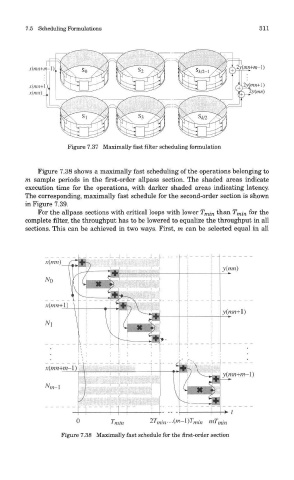
Figure 7.38 shows a maximally fast scheduling of the operations belonging to
m sample periods in the first-order allpass section. The shaded areas indicate
execution time for the operations, with darker shaded areas indicating latency.
The corresponding, maximally fast schedule for the second-order section is shown
in Figure 7.39.
For the allpass sections with critical loops with lower T mi n than T mi n for the
complete filter, the throughput has to be lowered to equalize the throughput in all
sections. This can be achieved in two ways. First, m can be selected equal in all
Figure 7.38 Maximally fast schedule for the first-order section