
Page 311 - DSP Integrated Circuits
P. 311
296 Chapter 7 DSP System Design
gray lines indicate that the delay elements carry signal values from one sample
interval to the next.
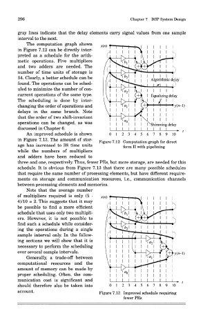
me computation grapn snown
in Figure 7.12 can be directly inter-
preted as a schedule for the arith-
metic operations. Five multipliers
and two adders are needed. The
number of time units of storage is
34. Clearly, a better schedule can be
found. The operations can be sched-
uled to minimize the number of con-
current operations of the same type.
The scheduling is done by inter-
changing the order of operations and
delays in the same branch. Note
that the order of two shift-invariant
operations can be changed, as was
discussed in Chapter 6.
An improved schedule is shown
in Figure 7.13. The amount of stor- Figure 7.12 Computation graph for direct
age has increased to 38 time units form II with pipelining
while the numbers of multipliers
ana aaaers nave oeen reaucea to
three and one, respectively. Thus, fewer PEs, but more storage, are needed for this
schedule. It is obvious from Figure 7.13 that there are many possible schedules
that require the same number of processing elements, but have different require-
ments on storage and communication resources, i.e., communication channels
between processing elements and memories.
Note that the average number
of multipliers required is only (5 •
4)/10 = 2. This suggests that it may
be possible to find a more efficient
schedule that uses only two multipli-
ers. However, it is not possible to
find such a schedule while consider-
ing the operations during a single
sample interval only. In the follow-
ing sections we will show that it is
necessary to perform the scheduling
over several sample intervals.
Generally, a trade-off between
computational resources and the
amount of memory can be made by
proper scheduling. Often, the com-
munication cost is significant and
should therefore also be taken into
account. Figure 7.13 Improved schedule requiring
fewer PEs