
Page 353 - DSP Integrated Circuits
P. 353
338 Chapter 7 DSP System Design
from the memory. Hence, two memory variables that share a memory cell
according to the memory schedule must be separated by 2Tj/ time slots.
Some of the PE-memory transactions require only one memory cycle. These
resources (i.e., a memory cell and a memory cycle) are not required if direct
interprocessor communication is allowed in the target architecture. However, here
we assume that this is not the case.
We have chosen to use two memories, since the adaptors have two inputs and
two outputs. We will use a modified version of the clique partitioning technique
just described to assign the variables to the memories. Instead of drawing a line
between processes that may share resources, we will draw a line between vertices
(memory variables) that can not be stored in the same memory or are accessed at
the same time instances. The reason for this is that the number of branches in the
graph otherwise becomes unmanageably large. The resulting exclusion graph is
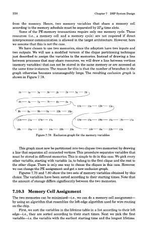
shown in Figure 7.78.
Figure 7.78 Exclusion graph for the memory variables
This graph must now be partitioned into two cliques (two memories) by drawing
a line that separates all connected vertices. This procedure separates variables that
must be stored in different memories. This is simple to do in this case. We pick every
other variable, starting with variable la, to belong to the first clique and the rest to
the other clique. There is only one way to choose the cliques in this case. However,
we can change the PE assignment and get a new exclusion graph.
Figures 7.79 and 7.80 show the two sets of memory variables obtained by this
choice. The variables have been sorted according to their starting times. Note that
the amount of storage differs significantly between the two memories.
7.10.3 Memory Cell Assignment
The two memories can be minimized—i.e., we can do a memory cell assignment—
by using an algorithm that resembles the left-edge algorithm used for wire routing
on the chip.
First, we sort the variables in the lifetime table in a list according to their left
edge—i.e., they are sorted according to their start times. Next we pick the first
variable—i.e. the variable with the earliest starting time and the longest lifetime.