
Page 355 - DSP Integrated Circuits
P. 355
340 Chapter 7 DSP System Design
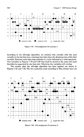
Figure 7.81 Cell assignment for memory 1
According to the left-edge algorithm, we combine this variable with the next
variable in the list that has a starting time later than the finishing time of the first
variable. However, each time step consists of a write followed by a read operation.
Two variables in Figures 7.79 and 7.80 that shall be stored in the same cell must
therefore be separated by one time slot. Otherwise the variables will overlap.
The results, after the left-edge algorithm has been applied, are shown in
Figures 7.81 and 7.82. The two memories must according to this scheme have six
Figure 7.82 Cell assignment for memory 2