
Page 359 - DSP Integrated Circuits
P. 359
344 Chapter 7 DSP System Design
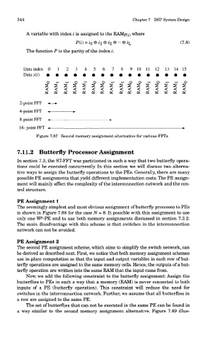
A variable with index i is assigned to the RAMp(j) where
The function P is the parity of the index i.
Figure 7.87 Second memory assignment alternative for various FFTs
7.11.2 Butterfly Processor Assignment
In section 7.3, the ST-FFT was partitioned in such a way that two butterfly opera-
tions could be executed concurrently. In this section we will discuss two alterna-
tive ways to assign the butterfly operations to the PEs. Generally, there are many
possible PE assignments that yield different implementation costs. The PE assign-
ment will mainly affect the complexity of the interconnection network and the con-
trol structure.
PE Assignment 1
The seemingly simplest and most obvious assignment of butterfly processes to PEs
is shown in Figure 7.88 for the case N = 8. It possible with this assignment to use
only one WP-PE and to use both memory assignments discussed in section 7.3.2.
The main disadvantage with this scheme is that switches in the interconnection
network can not be avoided.
PE Assignment 2
The second PE assignment scheme, which aims to simplify the switch network, can
be derived as described next. First, we notice that both memory assignment schemes
use in-place computation so that the input and output variables in each row of but-
terfly operations are assigned to the same memory cells. Hence, the outputs of a but-
terfly operation are written into the same RAM that the input came from.
Now, we add the following constraint to the butterfly assignment: Assign the
butterflies to PEs in such a way that a memory (RAM) is never connected to both
inputs of a PE (butterfly operation). This constraint will reduce the need for
switches in the interconnection network. Further, we assume that all butterflies in
a row are assigned to the same PE.
The set of butterflies that can not be executed in the same PE can be found in
a way similar to the second memory assignment alternative. Figure 7.89 illus-