
Page 357 - DSP Integrated Circuits
P. 357
342 Chapter? DSP System Design
Figure 7.83 First RAM assignment alternative
Memory Assignment 2
The second alternative is to always store the two input and output values to a but-
terfly in different memories. To develop such an assignment scheme we will first
study some small FFTs. Note that the unscrambling stage need not to be consid-
ered since this operation will be performed when data are written out of the FFT
processor.
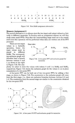
There are two input
values to a butterfly
operation, hence the
input values must be
stored in different
RAMs. The correspond-
ing exclusion graph will
therefore have a branch Figure 7.84 A two-point FFT and exclusion graph for
between vertices 0 and memories
1, as shown to the right
in Figure 7.84. For sim-
plicity we select to store the values with indices 0 and 1 in RAMo and RAMi,
respectively. Figure 7.84 shows the exclusion graph for the values in an in-place
computation of a two-point FFT.
A four-point FFT can be built out of two two-point FFTs by adding a first
stage, as shown in Figure 7.85. The constraints in the exclusion graph will come
from the first stage—i.e., there are exclusion branches between vertices 0—2 and
1-3. The constraints from the second stage are similar to the constraints obtained
for the two-point FFT.
Figure 7.85 A four-point ST-FFT and exclusion graph for memories