
Page 523 - DSP Integrated Circuits
P. 523
508 Chapter 11 Processing Elements
Figure 11.42 Parallel implementation of distributed arithmetic
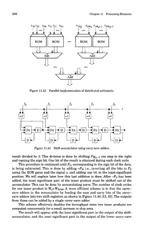
Figure 11.43 Shift-accumulator using carry-save adders
result divided by 2. This division is done by shifting Fyf d_i one step to the right
and copying the sign bit. One bit of the result is obtained during each clock cycle.
This procedure is continued until FQ, corresponding to the sign bit of the data,
is being subtracted. This is done by adding -Fo, i.e., inverting all the bits in FQ
using the XOR gates and the signal s, and adding one bit in the least-significant
position. We will explain later how this last addition is done. After -Fo has been
added, the most significant part of the inner product must be shifted out of the
accumulator. This can be done by accumulating zeros. The number of clock cycles
for one inner product is WJ+WROM- A more efficient scheme is to free the carry-
save adders in the accumulator by loading the sum and carry bits of the carry-
save adders into two shift registers as shown in Figure 11.44 [12, 35]. The outputs
from these can be added by a single carry-save adder.
This scheme effectively doubles the throughput since two inner products are
computed concurrently for a small increase in chip area.
The result will appear with the least significant part in the output of the shift-
accumulator, and the most significant part in the output of the lower carry-save