
Page 95 - DSP Integrated Circuits
P. 95
80 Chapter 3 Digital Signal Processing
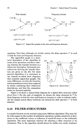
Figure 3.17 Signal-flow graphs in the time and frequency domains
1
equations. Note that, although not strictly correct, the delay operator z" is used
in both the time and frequency domains.
The signal-now graph is a struc-
tural description of the algorithm in
terms of its operations and their order-
ing, whereas the transfer function is a
behavioral description. Systematic pro-
cedures for deriving the transfer func-
tion are given in [32, 401. For more
general algorithms it is customary to
use instead so-called block diagrams
that resemble signal-flow graphs. The
main differences are that the branches
and transmittances have been replaced
by blocks containing their behavioral
descriptions, and that the summation
noaes are denoted explicitly.
Figure 3.18 shows a typical block diagram for a digital filter structure called
direct form I. For the sake of simplicity we denote the delay elements by T for
block diagrams in both the time and frequency domains in order to indicate explic-
1
itly the sample period. Many textbooks use instead the shift operator z" in both
domains.
3.13 FILTER STRUCTURES
A transfer function can be realized using many different algorithms. They may dif-
fer with respect to the number of arithmetic operations needed, sensitivity to devi-
ations in the coefficient values, or influence of round-off errors in the arithmetic
operations. The most important criterion for selecting a filter structure is its
robustness. That is, the algorithm should always be stable even under nonlinear