
Page 96 - DSP Integrated Circuits
P. 96
3.13 Filter Structures 81
usually described by signal-flow graphs instead of systems of difference equations.
Such signal-flow graphs are often called filter structures.
EXAMPLE 3.5
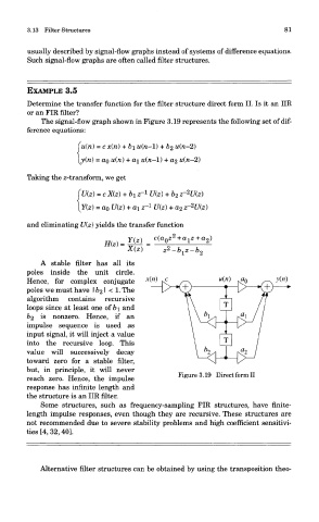
Determine the transfer function for the filter structure direct form II. Is it an IIR
or an FIR filter?
The signal-flow graph shown in Figure 3.19 represents the following set of dif-
ference equations:
Taking the z-transform, we get
and eliminating U(z) yields the transfer function
A stable filter has all its
poles inside the unit circle.
Hence, for complex conjugate
poles we must have 162' < 1- The
algorithm contains recursive
loops since at least one of b\ and
&2 is nonzero. Hence, if an
impulse sequence is used as
input signal, it will inject a value
into the recursive loop. This
value will successively decay
toward zero for a stable filter,
but, in principle, it will never
Figure 3.19 Direct form II
reach zero. Hence, the impulse
response has infinite length and
the structure is an IIR filter.
Some structures, such as frequency-sampling FIR structures, have finite-
length impulse responses, even though they are recursive. These structures are
not recommended due to severe stability problems and high coefficient sensitivi-
ties [4, 32, 40].
Alternative filter structures can be obtained by using the transposition theo-