
Page 166 - Decision Making Applications in Modern Power Systems
P. 166
130 Decision Making Applications in Modern Power Systems
Step 4: Convergence test
In this step the convergence of the method (5.3) is tested for any bus i,
with values in p.u. or real values.
_
ðkÞ
jjV j 2 jV _ ðk21Þ jj
ðkÞ i i
error 5 ; in p:u:values
i
V Base i
_
ðkÞ
jjV j 2 jV _ ðk21Þ jj ð5:3Þ
i
i
error ðkÞ 5 ; in real values
i
_
ðkÞ
jV j
i
For either case (real or p.u. values) the power flow algorithm converges
when error i 5 0:0001’i:
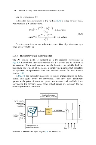
5.3.3 The photovoltaic system model
The PV system model is modeled as a PC element, represented in
Fig. 5.5. It combines the characteristics of a PV system and an inverter in
its structure. The model assumes that the inverter can quickly find the
maximum power point of the panel, a simplifying premise that considers
an optimized computational time with suitable results for most impact
studies [19].
In Fig. 5.5 the parameters necessary for system characterization in daily,
annual, and cyclic modes are represented. Thus three basic parameters
(power at the point of maximum power, temperature, and irradiation) are
provided to the software. Also, some critical curves are necessary for the
correct operation of the model.
FIGURE 5.5 OpenDSS PV object diagram [19]. PV, Photovoltaic.