
Page 169 - Decision Making Applications in Modern Power Systems
P. 169
Modeling and simulation Chapter | 5 133
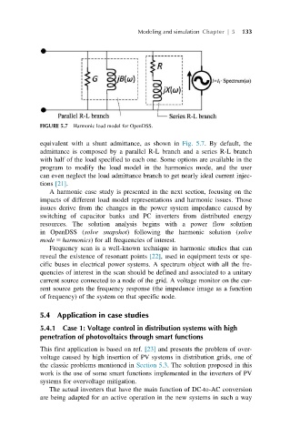
FIGURE 5.7 Harmonic load model for OpenDSS.
equivalent with a shunt admittance, as shown in Fig. 5.7. By default, the
admittance is composed by a parallel R-L branch and a series R-L branch
with half of the load specified to each one. Some options are available in the
program to modify the load model in the harmonics mode, and the user
can even neglect the load admittance branch to get nearly ideal current injec-
tions [21].
A harmonic case study is presented in the next section, focusing on the
impacts of different load model representations and harmonic issues. Those
issues derive from the changes in the power system impedance caused by
switching of capacitor banks and PC inverters from distributed energy
resources. The solution analysis begins with a power flow solution
in OpenDSS (solve snapshot) following the harmonic solution (solve
mode 5 harmonics) for all frequencies of interest.
Frequency scan is a well-known technique in harmonic studies that can
reveal the existence of resonant points [22], used in equipment tests or spe-
cific buses in electrical power systems. A spectrum object with all the fre-
quencies of interest in the scan should be defined and associated to a unitary
current source connected to a node of the grid. A voltage monitor on the cur-
rent source gets the frequency response (the impedance image as a function
of frequency) of the system on that specific node.
5.4 Application in case studies
5.4.1 Case 1: Voltage control in distribution systems with high
penetration of photovoltaics through smart functions
This first application is based on ref. [23] and presents the problem of over-
voltage caused by high insertion of PV systems in distribution grids, one of
the classic problems mentioned in Section 5.3. The solution proposed in this
work is the use of some smart functions implemented in the inverters of PV
systems for overvoltage mitigation.
The actual inverters that have the main function of DC-to-AC conversion
are being adapted for an active operation in the new systems in such a way