
Page 170 - Decision Making Applications in Modern Power Systems
P. 170
134 Decision Making Applications in Modern Power Systems
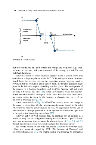
FIGURE 5.8 Volt/Var control.
that they control the PF, have support for voltage and frequency sags, inter-
act with the operator, and possess control of the voltage via Volt/Var and
Volt/Watt functions.
Volt/Var control for smart inverters operates using a custom curve that
controls the voltage regulation at the PCC. If the voltage is below the estab-
lished limit, the inverter acts on the capacitive region, injecting reactive
power, and if the voltage is above the set point, the inverter actuation takes
place in the inductive region, absorbing reactive power. The rated power of
the inverter is a limiting boundary, and Volt/Var function will not work
properly if it reaches this limit [24]. When the voltage is within the preestab-
lished operational limits, the region of the curve described with Dead Band,
no control action is taken by the inverter; a characteristic curve of the
function is presented in Fig. 5.8.
In the characteristic of Fig. 5.9 (Volt/Watt control), when the voltage in
the system is higher than V2, the output power decreases linearly to the point
P3, where the reactive power reduces to zero. An application for the use of
this function is the high penetration of PV systems in moments of light load
in the system that is causing overvoltage [23].
Volt/Var and Volt/Watt features may be identical for all devices in a
feeder, or they can be configured uniquely for each device. OpenDSS soft-
ware has a command that performs the characteristics of Figs. 5.8 and 5.9
through the iterative power flow solution algorithm described earlier.
The system chosen for the work simulations [23] was based on the IEEE
13-bus test feeder developed by IEEE (The Institute of Electrical and
Electronics Engineers) [24]. The original system was modified by connecting