Page 105 - Defrosting for Air Source Heat Pump
P. 105

Modeling study on uneven defrosting                                97


                   Heating mode             590 mm
                   Defrosting mode
                                                                       44 mm
                      T i
                      T i  SV 1
                 Header  T i                       Circuit 1           Circuit 1  152 mm
             From     T e  MV 1
            compressor
                          SV 2
            To compressor                                                22 mm
                                                   Circuit 2           Circuit 2
                      T e  MV 2
             To EEV                                                          500 mm
                          SV 3
            From EEV
                                                   Circuit 3
                       T e  MV 3                                       Circuit 3
                                                                      Measuring
                       Distributor
                                            Water collecting tray      cylinder
            (A)                               (slope 37  )


                   Heating mode             590 mm
                   Defrosting mode
                                                                       44 mm
                      T i
                      T i  SV 1
                 Header  T i                                           Circuit 1  152 mm
             From     T e  MV 1
            compressor                                           A
                          SV 2
            To compressor
                                                               A         22 mm
                      T e  MV 2                                        Circuit 2
             To EEV
                                                                 B           500 mm
                          SV 3
            From EEV
                                                               B
                       T e  MV 3                                       Circuit 3
                                                                 C    Measuring
                       Distributor
                                                                       cylinder
                                            Water collecting tray  C
            (B)                               (slope 37  )
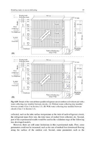
           Fig. 4.18 Details of the vertical three-parallel refrigerant circuit outdoor coil without and with a
           water-collecting tray installed between circuits. (A) Without water collecting tray installed
           between circuits (Case 1 in Section 3.3). (B) With water collecting tray installed between
           circuits (Case 3 in Section 3.3).

           collected, such as the tube surface temperature at the inlet of each refrigerant circuit,
           the refrigerant mass flow rate, the total mass of melted frost collected, etc. Second,
           part of the experimental results would be used in the validation stage of the following
           two developed models.
              However, there are still some limitations in this experimental study. First, some
           parameters could not be measured, such as the rate of melted frost downward flowing
           along the surface of the outdoor coil. Second, some parameters such as the
   100   101   102   103   104   105   106   107   108   109   110