
Page 100 - Defrosting for Air Source Heat Pump
P. 100
92 Defrosting for Air Source Heat Pump
8
Circuit 1
7 Circuit 2
Circuit 3
Temperature of melted water ( o C) 4 3 2
6
5
1
145 s 170 s
0
0 20 40 60 80 100 120 140 160 180 200 220 240
Defrosting time (s)
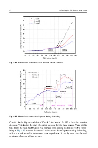
Fig. 4.14 Temperature of melted water on each circuit’s surface.
40 Circuit 1
Thermal resistance of refrigerant , 10 -4 (Km 2 )/W 25 Period 3 Period 5
Circuit 2
35
Circuit 3
30
20
Period 4
15
10
145 s
0 5 Period 1 85 s Period 2 170 s 190 s 225 s
0 20 40 60 80 100 120 140 160 180 200 220 240
Defrosting time (s)
Fig. 4.15 Thermal resistance of refrigerant during defrosting.
Circuit 1 is the highest and that of Circuit 3 the lowest. At 170 s, there is a sudden
decrease. This is also the start of a quick increase for the three curves. Thus, at this
time point, the main heat transfer role changed from heating the melted frost to vapor-
izing it. Fig. 4.15 presents the thermal resistance of the refrigerant during defrosting,
which is also impossible to measure in an experiment. It clearly shows the thermal
resistance changing at five periods.