
Page 106 - Defrosting for Air Source Heat Pump
P. 106
98 Defrosting for Air Source Heat Pump
temperature of the melted frost when it was downward flowing, were hardly impos-
sible to be measured. Third, some parameters were easy to measure, but not accurate
due to their fluctuations, such as the temperature of the air around the outdoor coil. In
the experimental study, this type of parameter was always measured by many sensors
and/or tested many times. Therefore, the following modeling study takes the respon-
sibility to measure the previous three types of parameters.
4.3.1.2 Modeling study
The development of the validated semiempirical model at the setting of without using
water-collecting trays between circuits for the experimental ASHP unit was separately
introduced previously. However, for the completeness of the current section, it is
briefly described here. The prototype of this model was Case 1 in the previous exper-
imental study. Details of the vertical three-circuit outdoor coil without a water-
collecting tray installed between circuits were shown in Fig. 4.18A, and a conceptual
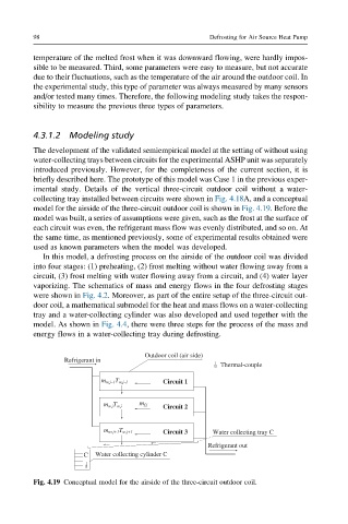
model for the airside of the three-circuit outdoor coil is shown in Fig. 4.19. Before the
model was built, a series of assumptions were given, such as the frost at the surface of
each circuit was even, the refrigerant mass flow was evenly distributed, and so on. At
the same time, as mentioned previously, some of experimental results obtained were
used as known parameters when the model was developed.
In this model, a defrosting process on the airside of the outdoor coil was divided
into four stages: (1) preheating, (2) frost melting without water flowing away from a
circuit, (3) frost melting with water flowing away from a circuit, and (4) water layer
vaporizing. The schematics of mass and energy flows in the four defrosting stages
were shown in Fig. 4.2. Moreover, as part of the entire setup of the three-circuit out-
door coil, a mathematical submodel for the heat and mass flows on a water-collecting
tray and a water-collecting cylinder was also developed and used together with the
model. As shown in Fig. 4.4, there were three steps for the process of the mass and
energy flows in a water-collecting tray during defrosting.
Outdoor coil (air side)
Refrigerant in
Thermal-couple
m w,j–1T w,j–1 Circuit 1
m w,jT w,j m f,j Circuit 2
m w, j+1T w,j+1 Circuit 3 Water collecting tray C
Refrigerant out
C Water collecting cylinder C
Fig. 4.19 Conceptual model for the airside of the three-circuit outdoor coil.