
Page 111 - Defrosting for Air Source Heat Pump
P. 111
Modeling study on uneven defrosting 103
(i) In the previous experimental study, the refrigerant mass flow rate in the three refrigerant
circuits was assumed to be evenly distributed. The calculated refrigerant mass flow rates
in the three circuits in the previous experimental study were derived following this
assumption.
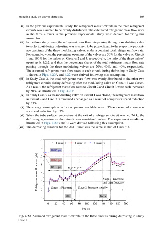
(ii) In the three study cases, the refrigerant mass flow rate passing through a modulating valve
to each circuit during defrosting was assumed to be proportional to the respective percent-
age openings of the three modulating valves, under a constant total refrigerant flow rate.
For example, when the percentage openings of the valves are 50% for the valve on Circuit
1 and 100% for the valves on Circuits 2 and 3, respectively, the ratio of the three valves’
openings is 1:2:2, and thus the percentage shares of the total refrigerant mass flow rate
passing through the three modulating valves are 20%, 40%, and 40%, respectively.
The assumed refrigerant mass flow rates to each circuit during defrosting in Study Case
1 shown in Figs. 4.20A and 4.22 were derived following this assumption.
(iii) In Study Case 2, the total refrigerant mass flow was evenly distributed to the other two
refrigerant circuits during defrosting after the modulating valve on Circuit 1 was closed.
As a result, the refrigerant mass flow rates to Circuit 2 and Circuit 3 were each increased
by 50%, as illustrated in Fig. 4.20B.
(iv) In Study Case 3, as the modulating valve on Circuit 1 was closed, the refrigerant mass flow
in Circuit 2 and Circuit 3 remained unchanged as a result of compressor speed reduction
by 33%.
(v) The energy consumption on the compressor would decrease 33% as a result of a compres-
sor speed reduction by 33%.
(vi) When the tube surface temperature at the exit of a refrigerant circuit reached 24°C, the
defrosting operation on that circuit was considered ended. The experiment conditions
illustrated in Figs. 4.20B and C were derived following this assumption.
(vii) The defrosting duration for the ASHP unit was the same as that of Circuit 3.
14
Circuit 1 Circuit 2 Circuit 3
12
10.83 g/s
Refrigerant mass flow rate (g/s) 8 6 4 10.10 g/s R > R > R 1 Stage 3: Decrease
10
10.62 g/s
3
2
and then fluctuate
Stage 1: Fluctuate
2
70 s Stage 2: Increase steadily
160 s
0
0 20 40 60 80 100 120 140 160 180 200
Time (s)
Fig. 4.22 Assumed refrigerant mass flow rate in the three circuits during defrosting in Study
Case 1.