
Page 108 - Defrosting for Air Source Heat Pump
P. 108
100 Defrosting for Air Source Heat Pump
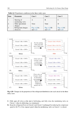
Table 4.2 Experiment conditions in the three study cases
Item Parameter Case 1 Case 2 Case 3
1 Opening of A B C
modulating valve
2 Other operational None None D
changes
3 Refrigerant changes Figs. 4.20A Figs. 4.20B Figs. 4.20C
shown in and 4.22 and 4.23 and 4.24
Circuit 1 (Re = 100%) Circuit 1 (Re = 95.6%)
Fix the opening
values since the
Circuit 2 (Re = 100%) Circuit 2 (Re = 101.1%)
start of defrosting
Circuit 3 (Re = 100%) Circuit 3 (Re = 103.3%)
(A)
Before After
Circuit 1 (Re = 100%) Closevalveon Circuit 1 (Re = 0%)
Circuit 1 when
Circuit 2 (Re = 100%) its defrosting Circuit 2 (Re = 150%)
was terminated
Circuit 3 (Re = 100%) Circuit 3 (Re = 150%)
(B) Before After
Close valve on
Circuit 1 (Re = 100%) Circuit 1 when Circuit 1 (Re = 0%)
its defrosting
was terminated
Circuit 2 (Re = 100%) Circuit 2 (Re = 100%)
Reduce the
Circuit 3 (Re = 100%) compressor Circuit 3 (Re = 100%)
speed to 66.7%
(C) Before After
Fig. 4.20 Changes in the proportion of the refrigerant distribution into each circuit in the three
study cases.
C. Fully open all valves at the start of defrosting, and fully close the modulating valve on
Circuit 1 when its defrosting was terminated.
D. Keep the refrigerant flows to Circuit 2 and Circuit 3 unchanged by reducing the compressor
speed to 66.7% of the original speed when the modulating valve on Circuit 1 is closed.