
Page 183 - Defrosting for Air Source Heat Pump
P. 183
Frosting evenness coefficient 177
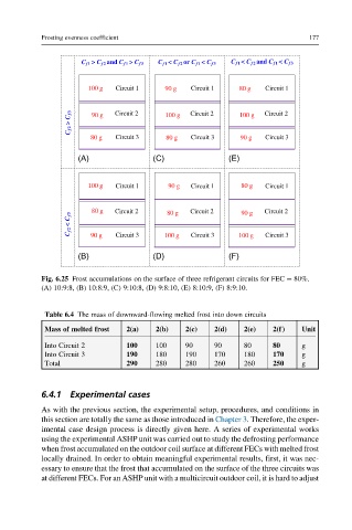
C f1 > C f2 and C f1 > C f3 C f1 < C f2 or C f1 < C f 3 C f 1 < C f2 and C f1 < C f3
100 g Circuit 1 90 g Circuit 1 80 g Circuit 1
C f2 > C f3 90 g Circuit 2 100 g Circuit 2 100 g Circuit 2
80 g Circuit 3 80 g Circuit 3 90 g Circuit 3
(A) (C) (E)
100 g Circuit 1 90 g Circuit 1 80 g Circuit 1
80 g Circuit 2 80 g Circuit 2 90 g Circuit 2
C f2 < C f3 90 g Circuit 3 100 g Circuit 3 100 g Circuit 3
(B) (D) (F)
Fig. 6.25 Frost accumulations on the surface of three refrigerant circuits for FEC ¼ 80%.
(A) 10:9:8, (B) 10:8:9, (C) 9:10:8, (D) 9:8:10, (E) 8:10:9, (F) 8:9:10.
Table 6.4 The mass of downward-flowing melted frost into down circuits
Mass of melted frost 2(a) 2(b) 2(c) 2(d) 2(e) 2(f) Unit
Into Circuit 2 100 100 90 90 80 80 g
Into Circuit 3 190 180 190 170 180 170 g
Total 290 280 280 260 260 250 g
6.4.1 Experimental cases
As with the previous section, the experimental setup, procedures, and conditions in
this section are totally the same as those introduced in Chapter 3. Therefore, the exper-
imental case design process is directly given here. A series of experimental works
using the experimental ASHP unit was carried out to study the defrosting performance
when frost accumulated on the outdoor coil surface at different FECs with melted frost
locally drained. In order to obtain meaningful experimental results, first, it was nec-
essary to ensure that the frost that accumulated on the surface of the three circuits was
at different FECs. For an ASHP unit with a multicircuit outdoor coil, it is hard to adjust