Page 186 - Defrosting for Air Source Heat Pump
P. 186

180                                         Defrosting for Air Source Heat Pump


                     28
                                Circuit 1     Circuit 2     Circuit 3
                     24
                   Temperature of tube surface ( o C)  16 8   193 s
                     20


                     12


                              o
                                                              197 s
                     0 4   1.87  C       125 s                193 s
                      80    100    120   140   160    180   200   220
                                           Time (s)
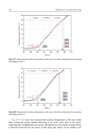
         Fig. 6.27 Measured tube surface temperatures at the exits of the three refrigerant circuits during
         defrosting in Case 1.


                     28
                              Circuit 1     Circuit 2     Circuit 3
                     24
                   Temperature of tube surface ( o C)  16 8  183 s
                     20


                     12


                     4
                              o
                          2.73  C
                                                            187 s
                                        122 s               186 s
                     0
                      80    100    120   140   160    180   200   220
                                           Time (s)
         Fig. 6.28 Measured tube surface temperatures at the exits of the three refrigerant circuits during
         defrosting in Case 2.

            Figs. 6.27–6.29 show the measured tube surface temperatures at the exits of the
         three refrigerant circuits during defrosting in the three cases. Due to the water-
         collecting trays installed between circuits, the melted frost was locally drained before
         it flowed downward into the down circuits along the surface of the outdoor coil.
   181   182   183   184   185   186   187   188   189   190   191