
Page 190 - Defrosting for Air Source Heat Pump
P. 190
184 Defrosting for Air Source Heat Pump
1.8
Circuit 1 Circuit 2 Circuit 3
1.5
1.2
Temperature ( o C) 0.9 T > T > T a1 T > T > T w3
w2
w1
0.6
a3
a2
135 s
0.3
130 s
0.0
130 s
–0.3
0 30 60 90 120 150 180 210 240
Time (s)
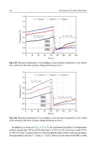
Fig. 6.35 Measured temperatures of surrounding air and measured temperature of the melted
frost collected in the three cylinders during defrosting in Case 2.
1.8
Circuit 1 Circuit 2 Circuit 3
1.5
T > T > T
1.2 a3 a2 a1
Temperature ( o C) 0.9
0.6
w2
w3
w1
0.3 125 s T > T ; T > T w3
125 s
0.0
115 s
–0.3
0 30 60 90 120 150 180 210 240
Time (s)
Fig. 6.36 Measured temperatures of surrounding air and measured temperature of the melted
frost collected in the three cylinders during defrosting in Case 3.
In addition, as shown in Figs. 6.27–6.29, the maximum deviations of temperature
of three circuits are 1.87°C at 125 s for Case 1, 2.73°C at 122 s for Case 2, and 3.73°C
at 120 s for Case 3, respectively. It is obvious that the order of the maximum deviation
of temperature is at Case 1 < Case 2 < Case 3. However, the order of the FECs of the