
Page 179 - Defrosting for Air Source Heat Pump
P. 179
Frosting evenness coefficient 173
frost coming from water-collecting Tray C. As shown in Fig. 6.22, at 187 s into
defrosting, the temperature curve order was observed at T 1 > T 2 > T 3 , although the
surrounding air temperature order was totally different at T 3 > T 2 > T 1 , as shown
in the first 140 s in Fig. 6.22. It could be concluded that the water temperature is
mainly decided by the heat transferred from the outdoor coil through the later warmer
melted frost flowing from the circuit to the tray and then to the cylinder. In addition,
the temperature curve order confirmed that less heat was taken from the outdoor coil
by melted frost for a higher FEC as a defrosting start for an ASHP unit. Therefore,
the negative effects of a lower FEC on the defrosting performance of an ASHP unit
with a multicircuit outdoor coil were further demonstrated.
6.3.3 Energy analysis and discussions
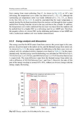
The energy used for the RCD comes from three sources: the power input to the com-
pressor, the power input to the indoor air fan, and the thermal energy from indoor air.
As shown in Fig. 6.23, the energy supplies for defrosting in the three cases were cal-
culated, with the calculated relative standard errors listed in Table 6.3. In this exper-
imental study, the total energy used for defrosting was calculated at 768.6 kJ in Case 1,
743.8 kJ in Case 2, or 3.2% less, and 648.8 kJ in Case 3, or 15.6% less than that in Case
1, respectively. The main difference came from the thermal energy from indoor air,
with a difference of 102.8 kJ between Case 1 and Case 3. However, the ratio of this
part of the energy was kept at around 83%–85%, without an obvious change with the
energy supply decreasing.
1,000
Input to the compressor and indoor air fan
900 Heat supply from indoor air
800 768.6 kJ
743.8 kJ
700 648.8 kJ
Energy supply (kJ) 600 644.0 kJ 632.6 kJ 541.2 kJ
500
(83.8%)
(83.4%)
(85.1%)
400
300
200
100
124.6 kJ 111.2 kJ 107.6 kJ
0
Case 1 Case 2 Case 3
Fig. 6.23 Energy supplies for defrosting in the three cases.