
Page 242 - Defrosting for Air Source Heat Pump
P. 242
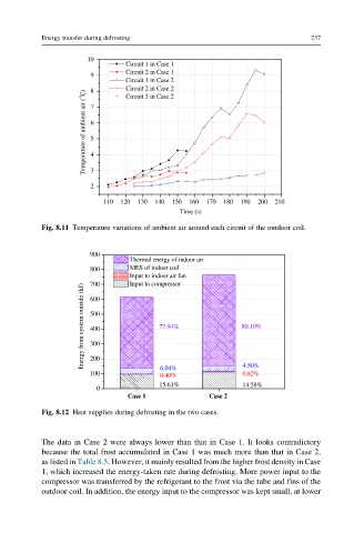
Energy transfer during defrosting                                 237


                      10
                                Circuit 1 in Case 1
                                Circuit 2 in Case 1
                       9
                                Circuit 1 in Case 2
                                Circuit 2 in Case 2
                       8
                      Temperature of ambient air ( o C)  7 6 5 4
                                Circuit 3 in Case 2


                       2 3
                          110  120  130  140  150  160  170  180  190  200  210
                                             Time (s)
           Fig. 8.11 Temperature variations of ambient air around each circuit of the outdoor coil.


                       900
                                 Thermal energy of indoor air
                       800       MES of indoor coil
                                 Input to indoor air fan
                                 Input to compressor
                       700
                     Energy from system outside (kJ)  500  77.94%  80.10%
                       600


                       400
                       300
                       200
                                                            0.82%
                       100              6.04%               4.50%
                                        0.40%
                                        15.61%              14.58%
                         0
                                Case 1              Case 2
           Fig. 8.12 Heat supplies during defrosting in the two cases.


           The data in Case 2 were always lower than that in Case 1. It looks contradictory
           because the total frost accumulated in Case 1 was much more than that in Case 2,
           as listed in Table 8.5. However, it mainly resulted from the higher frost density in Case
           1, which increased the energy-taken rate during defrosting. More power input to the
           compressor was transferred by the refrigerant to the frost via the tube and fins of the
           outdoor coil. In addition, the energy input to the compressor was kept small, at lower