
Page 243 - Defrosting for Air Source Heat Pump
P. 243
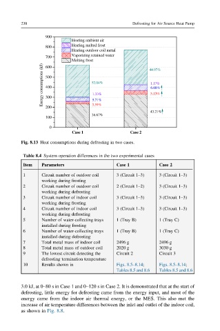
238                                         Defrosting for Air Source Heat Pump


                   900
                              Heating ambient air
                              Heating melted frost
                   800
                              Heating outdoor coil metal
                   700        Vaporizing retained water
                              Melting frost                 44.97%
                  Energy consumptions (kJ)  500  52.04%     1.17%
                   600


                   400
                                                            6.68%
                                                            5.13%
                                     1.33%
                   300
                                     5.71%
                   200               3.59%
                                                            43.21%
                                     38.67%
                   100
                    0
                             C  e s a  1            C  e s a  2
         Fig. 8.13 Heat consumptions during defrosting in two cases.


          Table 8.4 System operation differences in the two experimental cases
          Item   Parameters                    Case 1          Case 2
          1      Circuit number of outdoor coil  3 (Circuit 1–3)  3 (Circuit 1–3)
                 working during frosting
          2      Circuit number of outdoor coil  2 (Circuit 1–2)  3 (Circuit 1–3)
                 working during defrosting
          3      Circuit number of indoor coil  3 (Circuit 1–3)  3 (Circuit 1–3)
                 working during frosting
          4      Circuit number of indoor coil  3 (Circuit 1–3)  3 (Circuit 1–3)
                 working during defrosting
          5      Number of water-collecting trays  1 (Tray B)  1 (Tray C)
                 installed during frosting
          6      Number of water-collecting trays  1 (Tray B)  1 (Tray C)
                 installed during defrosting
          7      Total metal mass of indoor coil  2496 g       2496 g
          8      Total metal mass of outdoor coil  2020 g      3030 g
          9      The lowest circuit detecting the  Circuit 2   Circuit 3
                 defrosting termination temperature
          10     Results shown in              Figs. 8.5–8.14;  Figs. 8.5–8.14;
                                               Tables 8.5 and 8.6  Tables 8.5 and 8.6


         3.0 kJ, at 0–80 s in Case 1 and 0–120 s in Case 2. It is demonstrated that at the start of
         defrosting, little energy for defrosting came from the energy input, and most of the
         energy came from the indoor air thermal energy, or the MES. This also met the
         increase of air temperature differences between the inlet and outlet of the indoor coil,
         as shown in Fig. 8.8.