
Page 248 - Defrosting for Air Source Heat Pump
P. 248
Energy transfer during defrosting 243
Circuit 1 Circuit 1 Circuit 1 Circuit 1
m f,1 m f,1
m f,1 m f,1
Tray A Tray A
Circuit 2 Circuit 2 Circuit 2 Circuit 2
m f,2 m f,2 m f,2 m f,2
Tray B Tray B
Circuit 3 Circuit 3 Circuit 3
m f,3 m f,3 m f,3
Tray C
Frosting in Case 1 Defrosting in Case 1 Frosting in Case 2 Defrosting in Case 2
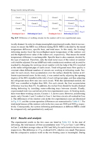
Fig. 8.15 Difference of working circuits for the outdoor coil in two experimental cases.
locally drained. In order to obtain meaningful experimental results, first it was nec-
essary to ensure the MES was different during RCD. MES is decided by the metal
temperature difference, specific heat, and total mass. In this study, the frosting/
defrosting modes fixed the lowest/highest metal temperature of the outdoor coil
and the highest/lowest value of the indoor coil, respectively. That means the metal
temperature difference is unchangeable. Specific heat is also constant, decided by
the type of material. Therefore, only the total metal mass of the indoor or outdoor
coil could be adjusted. For an ASHP unit with a multicircuit outdoor coil, it could be
reached by changing the working circuit number with the help of the SVs installed
at the outlet refrigerant pipe of each circuit. Total refrigerant mass flow quality is
constant when different numbers of circuits are working at defrosting mode. Sec-
ond, for each circuit, frost accumulation over the surface should be similar at dif-
ferent experimental cases. In this study, it was carried out by adjusting the opening
degrees of the MVs installed at the inlet of each refrigerant pipe, and thus adjusting
the refrigerant mass flow rate into each circuit. With this operational method, the
FEC was controlled at higher than 90%. For each circuit, the frost accumulation
difference was less than 5%. In addition, the melted frost should be locally drained
during defrosting by installing water-collecting trays between circuits. Finally,
experimental work was carried out at the two experimental cases. At frosting mode,
there were three working circuits, Circuits 1–3, in two cases. However, at defrosting
mode, only Circuits 1 and 2 worked in Case 1, but three circuits all worked in Case
2. The differences of the outdoor coils in the two experimental cases are illustrated
in Fig. 8.15, and the system operation differences are summarized in Table 8.7.The
total metal masses of the outdoor coils in the two cases are 2020 and 3030 g, respec-
tively. Consequently, the system defrosting performances at different MESs could
be comparatively and quantitatively analyzed.
8.3.2 Results and analysis
The experimental results in the two cases are listed in Table 8.8. At the start of
defrosting, the total masses of frost accumulation were 717 g in Case 1 and 1080 g
in Case 2, with their average values at 358.5 and 360 g for each circuit in the two cases,
respectively. The difference is 1.5 g, or about 0.41%, which is very small. That means
that the comparative analysis work on the two frosting cases is meaningful. During