
Page 244 - Defrosting for Air Source Heat Pump
P. 244
Energy transfer during defrosting 239
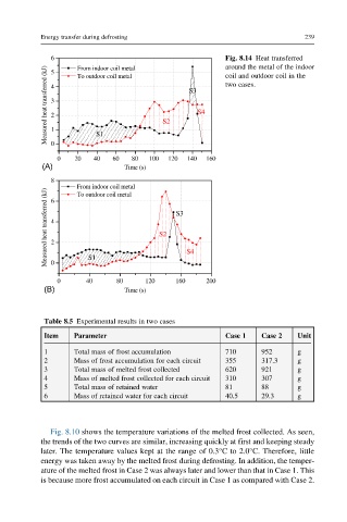
6 5 From indoor coil metal Fig. 8.14 Heat transferred
around the metal of the indoor
Measured heat transferred (kJ) 4 3 2 1 S2 S3 S4 two cases.
To outdoor coil metal
coil and outdoor coil in the
S1
0
0 20 40 60 80 100 120 140 160
(A) Time (s)
8
From indoor coil metal
Measured heat transferred (kJ) 4 2 S2 S3 S4
To outdoor coil metal
6
S1
0
0 40 80 120 160 200
(B) Time (s)
Table 8.5 Experimental results in two cases
Item Parameter Case 1 Case 2 Unit
1 Total mass of frost accumulation 710 952 g
2 Mass of frost accumulation for each circuit 355 317.3 g
3 Total mass of melted frost collected 620 921 g
4 Mass of melted frost collected for each circuit 310 307 g
5 Total mass of retained water 81 88 g
6 Mass of retained water for each circuit 40.5 29.3 g
Fig. 8.10 shows the temperature variations of the melted frost collected. As seen,
the trends of the two curves are similar, increasing quickly at first and keeping steady
later. The temperature values kept at the range of 0.3°C to 2.0°C. Therefore, little
energy was taken away by the melted frost during defrosting. In addition, the temper-
ature of the melted frost in Case 2 was always later and lower than that in Case 1. This
is because more frost accumulated on each circuit in Case 1 as compared with Case 2.