
Page 259 - Defrosting for Air Source Heat Pump
P. 259
254 Defrosting for Air Source Heat Pump
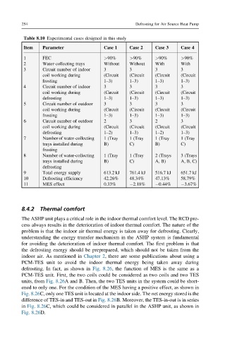
Table 8.10 Experimental cases designed in this study
Item Parameter Case 1 Case 2 Case 3 Case 4
1 FEC >90% >90% >90% >90%
2 Water-collecting trays Without Without With With
3 Circuit number of indoor 3 3 3 3
coil working during (Circuit (Circuit (Circuit (Circuit
frosting 1–3) 1–3) 1–3) 1–3)
4 Circuit number of indoor 3 3 3 3
coil working during (Circuit (Circuit (Circuit (Circuit
defrosting 1–3) 1–3) 1–3) 1–3)
5 Circuit number of outdoor 3 3 3 3
coil working during (Circuit (Circuit (Circuit (Circuit
frosting 1–3) 1–3) 1–3) 1–3)
6 Circuit number of outdoor 2 3 2 3
coil working during (Circuit (Circuit (Circuit (Circuit
defrosting 1–2) 1–3) 1–2) 1–3)
7 Number of water-collecting 1 (Tray 1 (Tray 1 (Tray 1 (Tray
trays installed during B) C) B) C)
frosting
8 Number of water-collecting 1 (Tray 1 (Tray 2 (Trays 3 (Trays
trays installed during B) C) A, B) A, B, C)
defrosting
9 Total energy supply 613.2 kJ 761.4 kJ 516.7 kJ 651.7 kJ
10 Defrosting efficiency 42.26% 48.34% 47.13% 58.79%
11 MES effect 0.33% 2.18% 0.44% 3.67%
8.4.2 Thermal comfort
The ASHP unit plays a critical role in the indoor thermal comfort level. The RCD pro-
cess always results in the deterioration of indoor thermal comfort. The nature of the
problem is that the indoor air thermal energy is taken away for defrosting. Clearly,
understanding the energy transfer mechanism in the ASHP system is fundamental
for avoiding the deterioration of indoor thermal comfort. The first problem is that
the defrosting energy should be preprepared, which should not be taken from the
indoor air. As mentioned in Chapter 2, there are some publications about using a
PCM-TES unit to avoid the indoor thermal energy being taken away during
defrosting. In fact, as shown in Fig. 8.26, the function of MES is the same as a
PCM-TES unit. First, the two coils could be considered as two coils and two TES
units, from Fig. 8.26A and B. Then, the two TES units in the system could be short-
ened to only one. For the condition of the MES having a positive effect, as shown in
Fig. 8.26C, only one TES unit is located at the indoor side. The net energy stored is the
difference of TES-in and TES-out in Fig. 8.26B. Moreover, the TES-in-out is in series
in Fig. 8.26C, which could be considered in parallel in the ASHP unit, as shown in
Fig. 8.26D.