
Page 303 - Defrosting for Air Source Heat Pump
P. 303
Defrosting control strategy 297
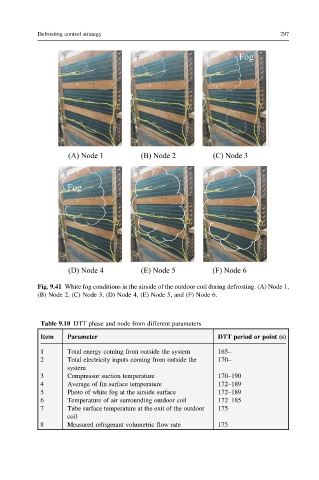
Fig. 9.41 White fog conditions in the airside of the outdoor coil during defrosting. (A) Node 1,
(B) Node 2, (C) Node 3, (D) Node 4, (E) Node 5, and (F) Node 6.
Table 9.10 DTT phase and node from different parameters
Item Parameter DTT period or point (s)
1 Total energy coming from outside the system 165–
2 Total electricity inputs coming from outside the 170–
system
3 Compressor suction temperature 170–190
4 Average of fin surface temperature 172–189
5 Photo of white fog at the airside surface 172–189
6 Temperature of air surrounding outdoor coil 172–185
7 Tube surface temperature at the exit of the outdoor 175
coil
8 Measured refrigerant volumetric flow rate 175