
Page 300 - Design and Operation of Heat Exchangers and their Networks
P. 300
286 Design and operation of heat exchangers and their networks
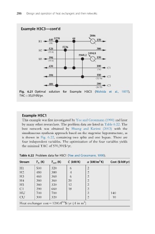
Example H3C3—cont’d
2806
5270 44
440 150
H1
(28)
5236
520 300
H2
(23.8)
2494.8
5569.2
390 150
H3
(33.6)
430 100
(16) C1
350 180 C2
(32.76)
400 200
C3
(26.35)
Fig. 6.21 Optimal solution for Example H3C3 (Nishida et al., 1977),
TAC¼35,010$/yr.
Example H5C1
This example was first investigated by Yee and Grossmann (1990) and later
by many other researchers. The problem data are listed in Table 6.22. The
best network was obtained by Huang and Karimi (2013) with the
simultaneous synthesis approach based on the stagewise hyperstructure, as
is shown in Fig. 6.22, containing two splits and one bypass. There are
four independent variables. The optimization of the four variables yields
the minimal TAC of 570,391$/yr.
Table 6.22 Problem data for H5C1 (Yee and Grossmann, 1990).
2
_
Stream T in (K) T out (K) C (kW/K) α (kW/m K) Cost ($/kWyr)
H1 500 320 6 2
H2 480 380 4 2
H3 460 360 6 2
H4 380 360 20 2
H5 380 320 12 2
C1 290 660 18 2
HU 700 700 2 140
CU 300 320 2 10
2
0.6
Heat exchanger cost¼1200A $/yr (A in m )