
Page 402 - Design and Operation of Heat Exchangers and their Networks
P. 402
Dynamic analysis of heat exchangers and their networks 385
ð
C f ¼ ρ c f δ f h f δ f ÞW=s f
f
1 2 2
C p, ijðÞ ¼ ρ c p δ p + δ f, ijðÞ δ =s f, ijðÞ + δ f, i 1, jð Þ δ =s f, i 1, jð W
p
2 f, ijðÞ f, i 1, jð Þ Þ
ð
U f ¼ 2α h f δ f ÞW=s f
ð
U p ¼ 2α s f δ f ÞW=s f
ð ½
K ¼ λ f δ f W= h f δ f Þs f
where W is the width of the heat exchanger, W¼130mm,
3
3
ρ¼995.61kg/m ,c¼4180J/kgK,ρ f ¼ρ p ¼2660kg/m ,c f ¼c p ¼860J/kgK,
andλ f ¼191.6W/mK.Theheattransfer coefficientsand thermalflowratesare
given in Table 7.4.
According to Fig. 7.13, the coordinate vectors and matching matrices
are given as follows:
T
m
^ 0
x ¼ 0, 0:925, 0, 0:925, 0:925, 1:24, 0:925, 1:24½ ðÞ
T
m
^ 00
x ¼ 0:925, 0, 0:925, 0, 1:24, 0:925, 1:24, 0:925½ ðÞ
000
Since there are no bypass connections from entrances to exits, G ¼0.
The nonzero elements of G, G , and G are.
00
0
0
0
0
0
0
g 48 ¼ g 51 ¼ g 73 ¼ 1, g ¼ g ¼ g ¼ g ¼ g ¼ 1,
11 23 31 64 82
00
00
00
00
g ¼ g ¼ 0:5, g ¼ g ¼ g ¼ 1
00
15 17 24 32 46
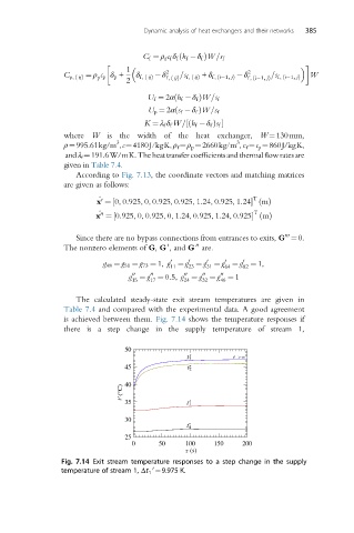
The calculated steady-state exit stream temperatures are given in
Table 7.4 and compared with the experimental data. A good agreement
is achieved between them. Fig. 7.14 shows the temperature responses if
there is a step change in the supply temperature of stream 1,
50
²
t 3
45 t 2 ²
t ²(°C) 40
35 t 1 ²
30
²
t 4
25
0 50 100 150 200
(s)
Fig. 7.14 Exit stream temperature responses to a step change in the supply
temperature of stream 1, Δt 1 ¼9.975 K.
0